My kids and I have spent many a weekend afternoon playing, learning, and exploring at Orlando Science Center. There is so much to see there that it’s easy to miss a little permanent exhibit in the hallway outside “The Hive” Makerspace on the 3rd floor. There you’ll find a pedestal against the wall with a spring on top and a little red button. People walk past it all the time, but tap the spring and the dark hallway comes to life with 8-bit sounds and light from an LED strip on the opposite wall.
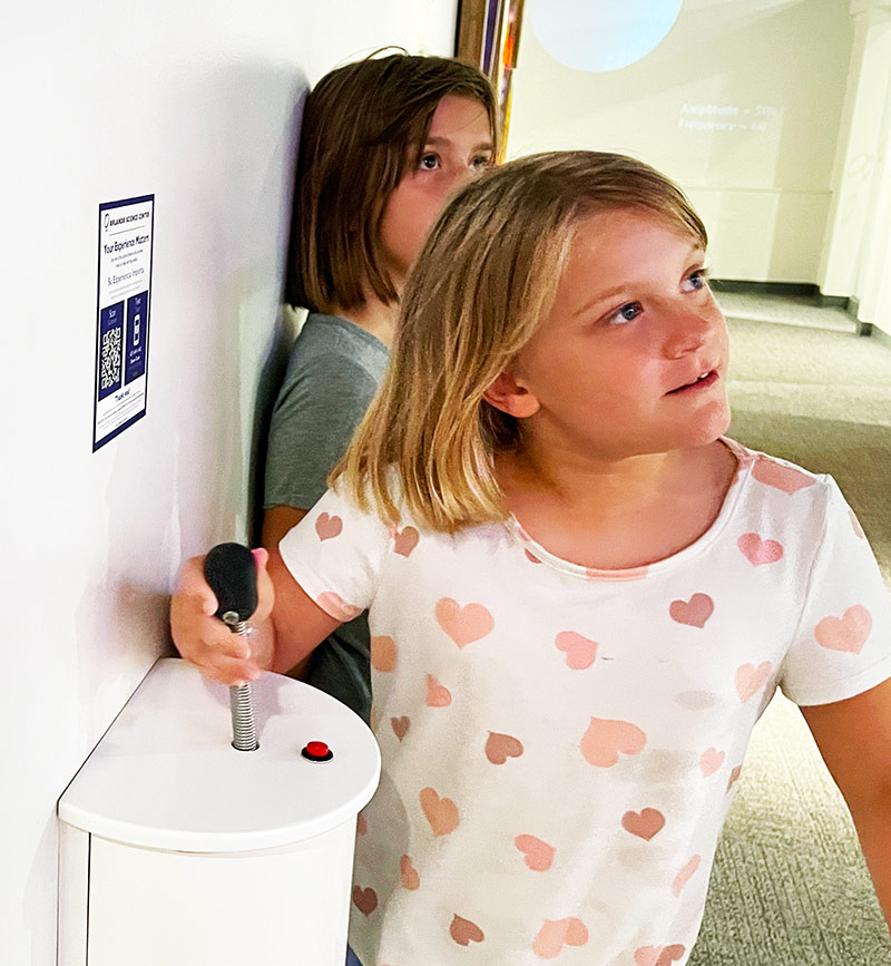
The exhibit is a brilliantly simple, 1-dimensional game called Line Wobbler by Robin Baumbgarten. The objective of the game is to move your character (a single green LED) from one end of the line to the other. Along the way, you encounter enemies that you can attack by wobbling the spring, flashing pools of lava, and conveyor belts that push you away from the finish line or fling you toward enemies. The analog nature of the spring controller makes the game surprisingly intuitive, fun to play, and challenging to master.

After playing Line Wobbler many times over the last few years, I stumbled upon https://github.com/Critters/TWANG – an Arduino-based, open-source game by a developer called Critters that was inspired by Line Wobbler. While the Github repo looked pretty straightforward, I had barely tinkered with Arduino in the past and didn’t think I had the skills to build one myself. We did get a 3d printer in December though, and when I told my 10yo about the project, she convinced me to give it a try.
Ordering Parts
Critters didn’t provide much in the way of DIY instructions, but doing a little more research, I found build details from 2 other makers:
- Building at TWANG by Bart Dring (buildlog.net)
- Building a Line Wobbler Clone with TWANG by Jim Groom (bavatuesdays.com)
I mostly followed Jim Groom’s details, but ran into a few issues to troubleshoot, so I thought I’d share my own experience. In addition to the parts below, I also used our 3D printer, a soldering iron, a hot glue gun, a wire stripper, heat shrink tubing and electrical tape.
| Item | Cost |
|---|---|
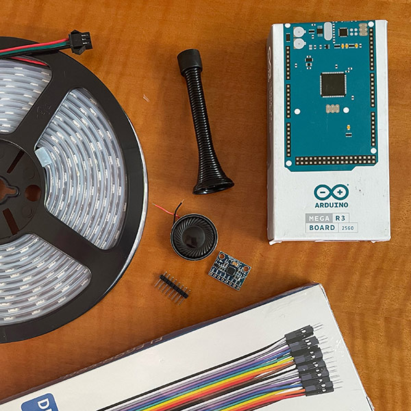
| Arduino Mega 2560 REV3 | $34.98 |
| WS2812B – ALITOVE 16.4ft 300 LED Strip | $32.99 |
| 4 Pack of 2W 8 Ohm Speakers | $10.40 |
| 120pcs Multicolored Dupont Wires | $6.99 |
| 2pcs 2.5m RGBW LED Strip Extension Cable (Note: Could replace w/ a 3pin cable with a JST SM connector.) |
$6.99 |
| Gy-521 3 Axis Accelerometer Module | $6.59 |
| 2-pack of black 3¼” Door Stoppers | $4.99 |
| 3M USB A to B Cable | $3.29 |
| Total | $107.22 |
3D Printed Enclosure

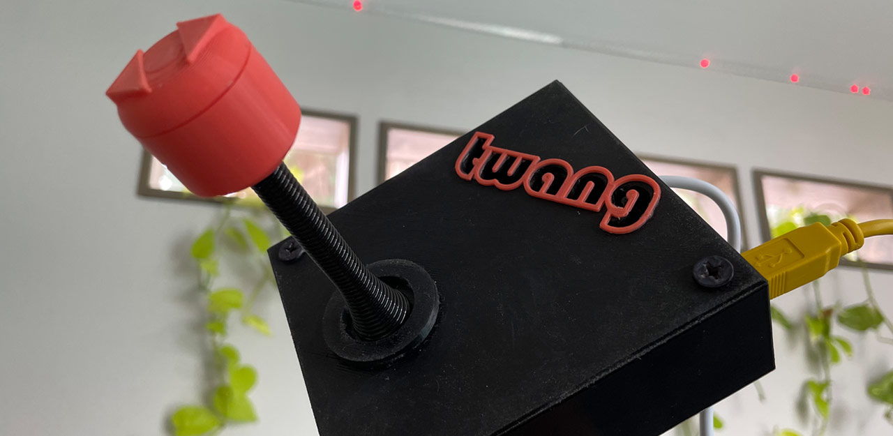
Once I had all the hardware, it was time to 3D print the case and topper. I started with Critter’s original obj files and made a few minor modifications in Tinkercad. The case itself was too short to fit Dupont connectors, so I made the box a little taller and added a hole for the dedicated power port on the Arduino Mega. In the end, I decided to power via USB, but it’s still nice to have the port accessible.
I also removed the speaker mount structure inside the case and made a much smaller one to fit the tiny speakers listed above that Jim Groom recommended. Finally, I created an outlined overlay of the “twang” audio hole to use as accent on the top of the case. I uploaded my modified set of thing files (in separate STLs) as a remix of Critters’ original set: https://www.thingiverse.com/thing:5390686

Assembly & Wiring
The first thing you need to do is press the Arduino Mega into the case. It should be a nice snug fit with the USB and power ports accessible. Then, connect the enclosure lid to the door stopper spring. To do that, twist the metal mounting plate off the broad end of the door stopper, pull the end of the wire out a bit with some pliers, and twist it through the hole in the top of the plate by at least a full thread. You also want to push and twist the topper base onto the other end of the spring. It’s a snug fit, but I put a little super glue inside to ensure it stays attached. We’ll be running wires through the spring, so it’s important to have all of that connected together before continuing. It’ll look something like this:
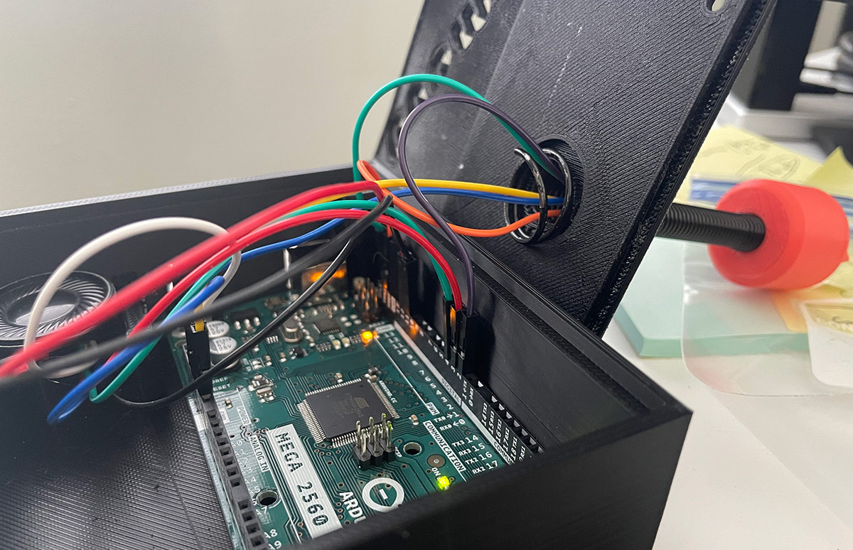
With our spring connected on both ends and Arduino board mounted, it’s time to start running wires. I made this diagram to show what connects where on the Arduino board.
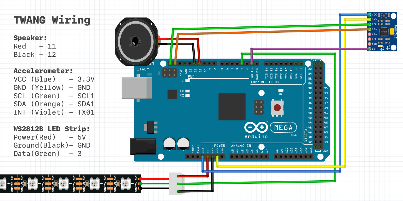
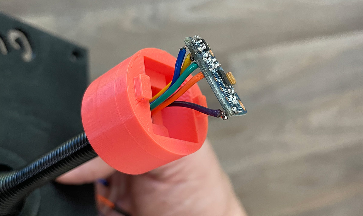
Outside of a few home improvement projects, I hadn’t done much soldering before, so I wanted to brush up on basic techniques. If you’re in the same boat, I’d recommend this Soldering Crash Course YouTube Video by wermy. Rather than using the set of pins included with the Accelerometer, I decided to clip the socket ends of the Dupont wires off and solder the bare wire of each directly to the 5 required pin holes on the accelerometer which are: VCC, GND, SCL, SDA, & INT
I knew that I wanted to mount our LED strip horizontally at the top of a wall, the way that Line Wobbler is set up at Orlando Science Center. To do that, I needed an extension cord. According to Jim Groom’s build, the 300 LED WS2812B strip can be powered off the 5V port on the Arduino and he mentioned that all 5 wires on the strip were used.
Because of that, I bought a set of 5 pin LED extension cords (in the parts list). I cut off 1 end of the extension, leaving a few inches of slack near the connector. I then cut off the black, 3pin JST-SM connector on the LED strip and soldered the Black, Green, and Red wires to the corresponding wires in my extension. I also connected the dedicated power and ground wire to the remaining 2 wires in the extension. We don’t actually need those, so you can skip that step or just use a 3-wire extension cord. I would recommend leaving them intact though in case you want to power the LED strip externally in the future.
Next, I soldered the 5 wires on the cut end of my long extension cord to the socket end of 5 Dupont wires. Again, you only need the Red, Green, and Black wire. The extension cord came with pin sets to connect the identical plug ends together, so soldering a plug on both the LED strip and the controller allows them to be disconnected.

Inside the case, I used a dab of hot glue to secure the extension insulation to the floor of the case and a little more to hold the speaker at the top of it’s mount. Here’s what it all looked like before closing it up. While I had the hot glue out, I also put a dab on the topper cap to keep it from flying off.

Installing the Code
The instructions that Jim Groom provided in his post for downloading the Arduino IDE, installing the necessary libraries, and pushing the code to your Arduino were great. As several people noted in the comments though, trying to upload the code results in compilation issues.
The WS2812B (NeoPixel type) LED strips do not have a clock wire, so I ended up resolving the issues by making sure the LED wires were plugged into the correct ports (see diagram above) and using the current version of Critters’ TWANG.ino file. All I had to do was update the following configuration settings and I was able to finally get it working.
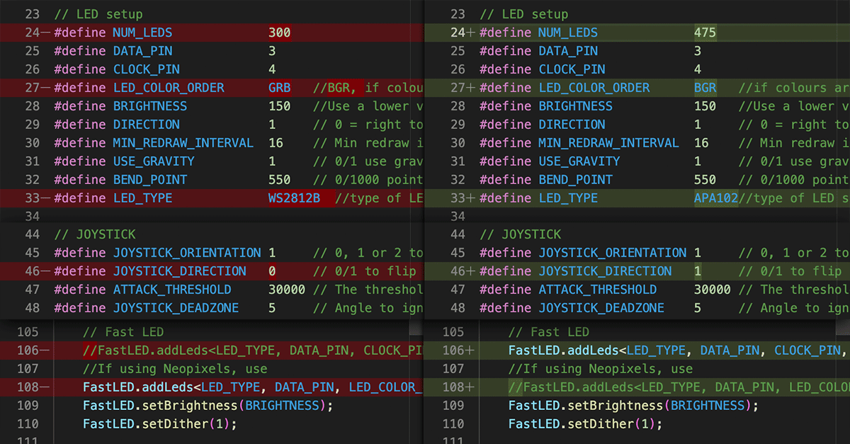
I love that Critters included a “screensaver” mode which you can see at the start of my first game play video below. Before correcting the LED_COLOR_ORDER config, the player dot was red, the enemies were green, and the lava was purple-ish. I liked the screensaver colors a lot better with those odd colors though, so it makes me want to tinker a bit with the code. For now though, I’ll just enjoy playing a new game with my kiddos.
